Do things I love, of course! That means it is time for more IT stuff, more electronics...
While I was digging through my boxes, I found these two external hard drive enclosures. I bought these cheaply a while back. The previous owners sold them cheaply because these are useless without power adapters. In this post, I am going to walk through how I got both of them working again.

Both enclosures have few things in common. One is that they both can connect to a computer via USB. Another is that they both utilize a mini-DIN connector for power connection.

Let's start with the black one. It's a standard 6-pin mini-DIN connector, identical to the S-Video connector. In order to find out the pin-out of the connector, I had to test each pin with a multimeter.

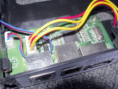
The design of this enclosure makes the test super easy. There is a 4-pin power connector that connects to the hard drive. The four pins are: 5 Volt (Red), Ground (Black), Ground (Black), and 12 Volt (Yellow).
There are three voltages involved, so a 3-conductor cable is needed. I employed a light-duty AC power cord for this. Here is the completed cable set.

The pin-out is as follows (looking at the pins on the plug):
Right set of two pins = Ground
Bottom set of two pins = 12 Volt
Left set of two pins = 5 Volt
Now let's move on to a more challenging one, shall we?

The silver one utilizes a standard (but uncommon) 5-pin mini-DIN connector. Like the exercise above, a multimeter is required to map the pins.

At first glance, there is no easy way to find out the power paths. I know the three voltages (12, 5, Ground) have to be there. Ground and 5 Volt can be found easily with the USB connector, but that still leave one voltage unconfirmed. The trick is to check the power pins on the serial-ATA connector.

The serial-ATA connector shown here is actually a combination of data (7 pins) and power (15 pins). The power pins are in groups of three for current capacity purposes. Here are the pins on the back of the circuit board:

Indeed, the "groups of three" are visible. Notice that the 3.3 Volt pins (first group of three) are not connected to anything.
With all the pins known, it's time to construct the cable.

For this enclosure, I employed an old keyboard plug/cable assembly from a dead keyboard. The keyboard connector is a 6-pin mini-DIN, so I had to break one of the pins off in order to fit. It feels good to recycle/re-use components from dead electronics.
This whole exercise is necessary because it's vital to check and confirm pin-outs of unfamiliar electronic devices. Never assume. Failure to do so may lead to permanent damage to the devices.