Showing posts with label Disclaimer. Show all posts

2015-11-29

Conquer the Origo Tower

Time for another fan repair post.

Unlike the last episode, this one is a used tower fan - Origo Crudus, also known as FTF36-LED. The fan has 3 speeds, sleep timer, natural rhythmic wind function, etc. One can control it through an infrared remote control, but unfortunately the remote is missing.

The original owner said the fan doesn't work; sometimes the fan will refuse to start. Since the price was real cheap, and, given the symptoms, I'm confident that I can fix it, I bought it for a learning experience.


The first thing I did to it was cleaning. The picture above was taken after hours of vacuuming and sanitizing.

As I powered it on for the first time under my ownership, there was no response except a temperature display:


Perhaps I am optimistic... this is a good sign, as this means the brains (likely a micro-controller) behind everything is working fine.

Before I continue, here is a friendly WARNING to viewers who wishes to try repairing their home appliances. Please read the disclaimer on this website. Most home appliances run on line voltage that can serious hurt or kill you. ALWAYS disconnect power before working on the appliance. My fan was unplugged during the whole repair process. If the appliance you need to work on is permanently attached to a connection unit on the wall (e.g. bathroom extractor fan), you have to switch off the power at the circuit breaker first. You should then confirm that the power is indeed off at the connection unit, as it's always possible to switch off the wrong breaker. As always, do NOT attempt the repair unless you absolutely 100% understand what you are doing and what the risks are.

Lets go right in. The following are close-up shots:


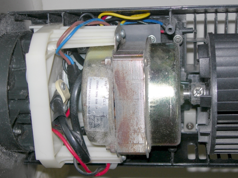
This is a 36" tower fan. A LED display and a few push buttons are at the top section, while the fan motor and the oscillation motor are at the base section. A long multi-conductor cable connects these two sections together.

Interestingly, the power supply board, which provides low voltage for the micro-controller, LEDs, TRIACs, and all other electronics, is located at the base section behind the fan motor.

Like the last fan repair scenario, a faulty power supply (due to bad capacitors) was the first thing on my mind. Lets inspect that:


The 1.2 uF CBB61 capacitor on the left is for the fan motor. The large and yellow 2 uF capacitor is a critical component at the beginning section of the non-isolated capacitive power supply. There are five TRIACs to enable the micro-controller to interface with mains voltage control. A very common design.

Learning from experience, I removed the two yellow capacitors for testing:


The ones on the left are bad parts, right are replacements. It is hard to imagine how far off the capacitance values are!

CG-Elec X2 0.1 uF = 0.405 micro-farad (less than 50% of spec.)

CG-Elec X2 2.0 uF = 0.513 micro-farad (roughly 25% of spec.)

Tenta X2 0.1 uF = 0.104 micro-farad (looks good)

Epcos X2 2.2 uF = 1.95 micro-farad (within spec, as B32924 M-class has a tolerance of ± 20%)


Just like my last repair session, I used an Epcos MKP X2 capacitor.


The soldering of the incoming AC wires were a mess, so I fixed those when I put the replacement capacitors in.

This should restore the right amount of power to all electronics, and conclude this exercise. Well, not really.

The fan would turn on (motor spins) when I press the power button. However, if I press the other buttons, like timer or speed, the fan would stop responding. Something tells me there are more problems with this fan. Time to look at the micro-controller circuitry:


The micro-controller is clearly labelled as "MCU1", right next to a buzzer. Noting the temperature display and the fan motor engagement, I know the micro-controller has to be fine. Otherwise, nothing would work.

What's left are the push-buttons:


A quick probing with a multimeter in continuity mode showed that all but two are bad - contact sticking when after being depressed.

This explains the non-responding controls. When buttons are stuck enabled, the micro-controller isn't expecting such situation to happen, thus simply hangs.


The old tactile switches are somehow rusty. This seemed really odd, as the switches are mounted internally, away from the elements like moisture.

I bought a pack of five new switches, so I had to reuse one that is still working.


After replacing the switches, the fan is in full working order.


After observing the fan operating for a few days, I am pleased to see that the repair is a success.

2013-09-11

Easy Window Air Conditioner Repair

Recently, a close-relative complained to me about some problems with the air conditioners in his home. The apartment he lives in is a rental property, so replacement is not an option. Since he lacks the necessary repair knowledge, I took a look for him. The repair was surprisingly easy, so I thought it would be a great idea to share.


As illustrated above, his air conditioners are the packaged type that is installed through a wall or window. Such unit is designed to cool a single room.

There were two units with similar problems. The first one I looked at is an old Made-in-China no-name unit, with a cooling capacity of 12000 BTU and uses R-22 refrigerant. The unit runs, but the user complained about compressor shutdown during hot days. On those days, the unit would start up fine and output cool air. Yet, sometime after start, the unit would not cool anymore (but the fan continues to run). If the outside temperature drops, the unit would be back to normal operation on its own.

I was also told that the drain has blocked recently. The user was able to fix that himself. A part of the fix, he rinsed the condenser coils with soap and water. Such testimony led me to believe that airflow restriction due to condenser coil blockage is the cause.

Enough speculating - It's time to take a closer look at the unit. Before I continue, here is a friendly WARNING to viewers who wishes to try repairing their home appliances. Please read the disclaimer on this website. Most home appliances run on line voltage that can serious hurt or kill you. ALWAYS disconnect power before working on the appliance. The unit was unplugged during the whole repair process. If the appliance you need to work on is permanently attached to a connection unit on the wall (e.g. bathroom extractor fan), you have to switch off the power at the circuit breaker first. You should then confirm that the power is indeed off at the connection unit, as it's always possible to switch off the wrong breaker. As always, do NOT attempt the repair unless you absolutely 100% understand what you are doing and what the risks are. 

Obviously, the front cover had to be removed:


Like I mentioned earlier, this is an old unit. The dust and stain shown are typical. The power cable is routed to where the controls are, so there must be something behind the knobs.


There we go. Since the unit utilized non-electronic control, the troubleshooting process was really simple. In fact, the potential culprits are in plain sight - capacitors. The large rusted can (CBB65) is a run capacitor for the compressor, while the black rectangular one (CBB61) is a run capacitor for the fan motor.


CBB65, label = 35 micro-farad ± 5% (33.25 - 36.75)
CBB65, meter = 34.9 micro-farad (0.3% less than labelled value)
CBB61, label = 3 micro-farad ± 5% (2.85 - 3.15)
CBB61, meter = 2.44 micro-farad (19% less than labelled value)

Just as I suspected, the run capacitor for the fan motor is the fault. With a faulty capacitor, the fan runs at reduced speed. This reduced cooling efficiency of the condenser coil to the point that the compressor overheats and triggers the automatic thermal overload shut-off.

Typically, if the meter reading is within 10% then the capacitor is still considered acceptable. The CBB61 here is definitely not. The only method of repair is to replace the faulty capacitor with a new one.

With this unit fixed, it is time to move on to another one with similar but more severe problems. Again, I began by removing the front cover:


This is yet another old Made-in-China no-name unit, with a cooling capacity of 7500 BTU and uses R-22 refrigerant. The unit would hum/buzz when powered on. Since this unit was located in a bedroom, the user rarely uses it due to the noise.

Hum/buzz is a common symptom of a dying capacitor on an electric motor, so I knew this would be another quick one.


The design is common among units with non-electronic control. The large blue can (CBB65) is a run capacitor for the compressor, while the black rectangular one (CBB61) is a run capacitor for the fan motor.


CBB65, label = 17 micro-farad ± 5% (16.15 - 17.85)
CBB65, meter = 16.8 micro-farad (1% less than labelled value)
CBB61, label = 3 micro-farad ± 5% (2.85 - 3.15)
CBB61, meter = 0.737 micro-farad (75% less than labelled value)


Although the multimeter I used was a trustworthy Fluke 87-5, I still couldn't believe the reading at the first test of the CBB61. No wonder the fan motor would hum/buzz like no tomorrow! Just like the previous case, the only method of repair is to replace the faulty capacitor with a new one.

Speaking of the new capacitor:


All the specifications (capacitance, voltage rating, operation temperature rating) of the new one are identical to those on the faulty one. 

It is worth noting that, after the capacitor replacement, both units not only work normally, but also blow much stronger stream of air. 

2012-06-03

Easy Fan Repair

A few years ago, my father bought this nice fan.


It's a Sunpentown (Taiwanese home appliance manufacturer) 14" stand fan. It has 3 speeds, infrared remote control, sleep timer, natural rhythmic wind function, etc. Height is adjustable on a telescopic column.

Like many high-end fans on the market today, this fan utilizes an additional small motor, instead of a reduction gear box driven by the fan motor, for the oscillation. In other words, the oscillation is triggered electronically (to power that small motor) instead of mechanically.

The fan worked great until last year, when a strange symptom began to appear. Whenever the fan is running, the fan will abruptly turn itself off if the oscillation is engaged. Selection of the rhythmic wind function will trigger this "instant shut-off" symptom too. Strangely, the fan can start right up again if one presses the on/off button. Other functions like the timer are fine. The on-board 1.5 A fuse has not been blown.

With summer here and fan usage increases, I believe now is a good time to fix this.

Before I continue, here is a friendly WARNING to viewers who wishes to try repairing their home appliances. Please read the disclaimer on this website. Most home appliances run on line voltage that can serious hurt or kill you. ALWAYS disconnect power before working on the appliance. My fan was unplugged during the whole repair process. If the appliance you need to work on is permanently attached to a connection unit on the wall (e.g. bathroom extractor fan), you have to switch off the power at the circuit breaker first. You should then confirm that the power is indeed off at the connection unit, as it's always possible to switch off the wrong breaker. As always, do NOT attempt the repair unless you absolutely 100% understand what you are doing and what the risks are.

Like most repair scenarios, full dis-assembly was the first thing to do. Due to the location, the fan motor housing was the first section I inspected.


The fan works fine at all 3 speeds, so I believe the fan motor and the starting capacitor are fine. Originally, I thought the small oscillator motor is dead. That assumption is wrong, as a simple hookup to 220 VAC proved that it works. The problem was definitely somewhere else - the base of the fan.

After removing the base (secured with a screw ring) and 6 screws, I found a circuit board that all wires connect to:


On first sight, the fact that the red AC capacitor is connected on the copper side of the circuit board really surprised me. This capacitor is a critical component at the beginning section of the non-isolated capacitive power supply. The power supply is used to generate low voltage for the electronics (LEDs, TRIACs, PIC, etc. - more on these below). It is hard to imagine how this important component was "left out" during circuit board layout (and thus have to be tagged on at the back). Well, enough about that. Let's look at the component side:


First off, a little tour around the circuit board.

The large IC chip is a microcontroller - a PIC16C57C in 28-pin DIP made by Microchip Technology Inc. There are eight LEDs to show fan status like current speed and timer settings. The black component next to the LEDs is an infrared sensor to receive the signals sent by the remote control. Surrounding the 470 uF electrolytic capacitor are five buttons to control the fan. A piezoelectric buzzer (circular black component next to the on/off button) provides audio feedback. On the bottom of the picture, numerous wires connects to the circuit board. From left to right, they are:

Grey - Connects to oscillator motor.
Brown - Connects to fan motor low-speed winding.
Pink - Connects to fan motor medium-speed winding.
Yellow - Connects to fan motor high-speed winding.
Blue - Input from the neutral wire of AC plug.
White - Connects to the motor starting capacitor, then to both motors. Basically a shared live wire after the fuse.
Brown - Input from the live wire of AC plug. Connects to the fuse.

An interesting point I noted was that the first four wires in the list above are all connected similarly. Upstream from each wire is a transistor-looking (TO-92 package) component named "97A8" and a corresponding resistor. A quick search on the Internet showed that it's actually a logic-level TRIAC with a maximum voltage of 600 V. The exact model for this component is MAC97A8. Basically, the TRIAC is like a on/off switch. When one of its legs, named Gate, receives a signal (sent from the microcontroller in this case), AC power is allowed to flow through the two other legs of the TRIAC.

The four TRIACs are in excellent shape so I believe the problem is before the TRIACs. That brings me to the microcontroller. The microcontroller has to be fine. Otherwise, nothing would work. The software (code) is out of consideration because it cannot be modified by this circuit. Looking back at the symptom, and reading this article from Microchip, I believe the malfunction has to do with the microcontroller shutting itself off (reset) due to brown out. It only exists when the rhythmic wind function or oscillation is engaged. I wondered why only these two functions, not other functions like speed change or timer, would cause this. 

By using a flow-chart to analyze how the microcontroller would control the fan if I were to program it from scratch (but with this existing circuit), I discovered an interesting point. When the fan motor is running, only one out of the three TRIACs connected to the fan motor is triggered by the microcontroller at any time. That makes sense because the fan motor cannot be in two different speeds at the same time. Moreover, the oscillator motor can only be turned on when the fan motor is running. To turn on that motor, the microcontroller triggers the corresponding TRIAC. When this happens, the microcontroller is now triggering two TRIACs at the same time. This is also when the "instant shut-off" symptom appears immediately. 

This finding, combines with the fact that the malfunction is likely to be related to age of the fan, turned me to the power supply section of the circuit. It is a non-isolated capacitive power supply with half-wave rectification. Capacitor is almost always the culprit when it comes to unusually-large voltage drop on high load or other weird power issues, and almost always the first type of component to die as time passes, so it's time for a change. 


The capacitors in question were two metalized polyester film (MEF) non-polarized capacitors, both made by UTX and rated for 400 V operation. The large one is "105K" (or 1 uF / 1000 nF) and the small one is "104K" (or 0.1 uF / 100 nF). 

That 470 uF electrolytic capacitor should be replaced as well, but its role isn't as critical as those two, so I didn't touch it.

Replacements are of the same construction (MEF type) and value, but with a higher voltage rating (630 V) and from a different (more reputable, in my opinion) manufacturer - Epcos, which is now TDK-EPC. My point of purchase for the new capacitors was RS Components. After acquiring the components, it's just a simple process of replacement using a soldering iron. 


Since the new capacitors are larger than the old ones due to the increased voltage rating, I had to juggle and be creative with placement. The smaller one fitted in without much difficulty. It's installed at an angle in order to utilize an existing hole on the circuit board.


The big one was not as easy though. Due to the extra-large size, limited board real estate, and re-use of existing holes, I had to use jumper wires. Heat-shrink tubing and electrical tape were added to keep exposed conductors away from the neighbors.


Instead of hanging on the back side of the circuit board, the big capacitor now safely and neatly reside in a space next to the telescopic stand section.

After observing the fan operating for a few days, I am pleased to see that the repair is a success.


2009-01-11

Disclaimer

Terms of Use

By using/viewing this website, you (the user/viewer of this website) are agreeing to comply with and be bound by the following terms and conditions of use. If you disagree with any part of these terms and conditions, please stop using/viewing this website.

The using/viewing of this website is subject to the following terms of use:
  • The information contained in this website is for my own documentation and exhibition purposes only. 
  • The content of the pages of this website is subject to change without notice.
  • I aim to keep the information on this blog as current, accurate and complete as possible. However, I do not provide any warranty or guarantee as to the accuracy, timeliness, performance, completeness or suitability of the information and materials found or offered on this website for any particular purpose. You acknowledge that such information and materials may contain inaccuracies or errors and I expressly exclude liability for any such inaccuracies or errors to the fullest extent permitted by law.
  • Your use of any information or materials on this website is entirely at your own risk, for which I shall not be liable. In other words, under no circumstances will I be liable for any consequence relating directly or indirectly to any action or inaction you take based on the information, services or other material on this website. It shall be your own responsibility to ensure that any information available through this website meet your specific requirements. In no event will I be liable for any loss or damage including without limitation, indirect or consequential loss or damage, or any loss or damage whatsoever arising from loss of data or profits arising out of, or in connection with, the use of this website.
  • This website contains material which is owned by or licensed to me. This material includes, but is not limited to, the design, layout, look, appearance and graphics. Reproduction is prohibited other than in accordance with the copyright notice, which forms part of these terms and conditions.
  • All trade marks reproduced in this website which are not the property of, or licensed to, the operator are acknowledged on the website.
  • Unauthorised use of this website may give rise to a claim for damages and/or be a criminal offence.
  • This website contains links to other websites. These links are provided for your convenience to provide further information. The inclusion of any links does not necessarily imply a recommendation or endorse the views expressed within them. I have no control over the availability of the linked websites.
  • This website is hosted by Google Inc. Blogger service. I take no responsibility for, and will not be liable for, this website being temporarily unavailable due to technical issues beyond my control.

Copyright

This website and its content is copyright of BEpsilon - © BEpsilon 2009. All rights reserved.
Any redistribution or reproduction of part or all of the contents in any form is prohibited other than the following:
  • you may print or download to a local hard disk extracts for your personal and non-commercial use only.
  • you may copy the content to individual third parties for their personal use, but only if you acknowledge the website as the source of the material.
You may not, except with my express written permission, distribute or commercially exploit the content. Nor may you transmit it or store it in any other website or other form of electronic retrieval system.