Showing posts with label Electronics. Show all posts

2015-11-29

Conquer the Origo Tower

Time for another fan repair post.

Unlike the last episode, this one is a used tower fan - Origo Crudus, also known as FTF36-LED. The fan has 3 speeds, sleep timer, natural rhythmic wind function, etc. One can control it through an infrared remote control, but unfortunately the remote is missing.

The original owner said the fan doesn't work; sometimes the fan will refuse to start. Since the price was real cheap, and, given the symptoms, I'm confident that I can fix it, I bought it for a learning experience.


The first thing I did to it was cleaning. The picture above was taken after hours of vacuuming and sanitizing.

As I powered it on for the first time under my ownership, there was no response except a temperature display:


Perhaps I am optimistic... this is a good sign, as this means the brains (likely a micro-controller) behind everything is working fine.

Before I continue, here is a friendly WARNING to viewers who wishes to try repairing their home appliances. Please read the disclaimer on this website. Most home appliances run on line voltage that can serious hurt or kill you. ALWAYS disconnect power before working on the appliance. My fan was unplugged during the whole repair process. If the appliance you need to work on is permanently attached to a connection unit on the wall (e.g. bathroom extractor fan), you have to switch off the power at the circuit breaker first. You should then confirm that the power is indeed off at the connection unit, as it's always possible to switch off the wrong breaker. As always, do NOT attempt the repair unless you absolutely 100% understand what you are doing and what the risks are.

Lets go right in. The following are close-up shots:


This is a 36" tower fan. A LED display and a few push buttons are at the top section, while the fan motor and the oscillation motor are at the base section. A long multi-conductor cable connects these two sections together.

Interestingly, the power supply board, which provides low voltage for the micro-controller, LEDs, TRIACs, and all other electronics, is located at the base section behind the fan motor.

Like the last fan repair scenario, a faulty power supply (due to bad capacitors) was the first thing on my mind. Lets inspect that:


The 1.2 uF CBB61 capacitor on the left is for the fan motor. The large and yellow 2 uF capacitor is a critical component at the beginning section of the non-isolated capacitive power supply. There are five TRIACs to enable the micro-controller to interface with mains voltage control. A very common design.

Learning from experience, I removed the two yellow capacitors for testing:


The ones on the left are bad parts, right are replacements. It is hard to imagine how far off the capacitance values are!

CG-Elec X2 0.1 uF = 0.405 micro-farad (less than 50% of spec.)

CG-Elec X2 2.0 uF = 0.513 micro-farad (roughly 25% of spec.)

Tenta X2 0.1 uF = 0.104 micro-farad (looks good)

Epcos X2 2.2 uF = 1.95 micro-farad (within spec, as B32924 M-class has a tolerance of ± 20%)


Just like my last repair session, I used an Epcos MKP X2 capacitor.


The soldering of the incoming AC wires were a mess, so I fixed those when I put the replacement capacitors in.

This should restore the right amount of power to all electronics, and conclude this exercise. Well, not really.

The fan would turn on (motor spins) when I press the power button. However, if I press the other buttons, like timer or speed, the fan would stop responding. Something tells me there are more problems with this fan. Time to look at the micro-controller circuitry:


The micro-controller is clearly labelled as "MCU1", right next to a buzzer. Noting the temperature display and the fan motor engagement, I know the micro-controller has to be fine. Otherwise, nothing would work.

What's left are the push-buttons:


A quick probing with a multimeter in continuity mode showed that all but two are bad - contact sticking when after being depressed.

This explains the non-responding controls. When buttons are stuck enabled, the micro-controller isn't expecting such situation to happen, thus simply hangs.


The old tactile switches are somehow rusty. This seemed really odd, as the switches are mounted internally, away from the elements like moisture.

I bought a pack of five new switches, so I had to reuse one that is still working.


After replacing the switches, the fan is in full working order.


After observing the fan operating for a few days, I am pleased to see that the repair is a success.

2013-11-20

Fix my Saab lights 3

Time for more light-related repairs and mods in my Saab.

Of all the cars I come across on the street or in the parking lot, most have a security system in it. A common sign of the existence of such system is a visible light-emitting diode (LED) flashing somewhere on the dash. It is not only an indicator of system operation, but also a deterrent - telling would-be thieves to stay away.

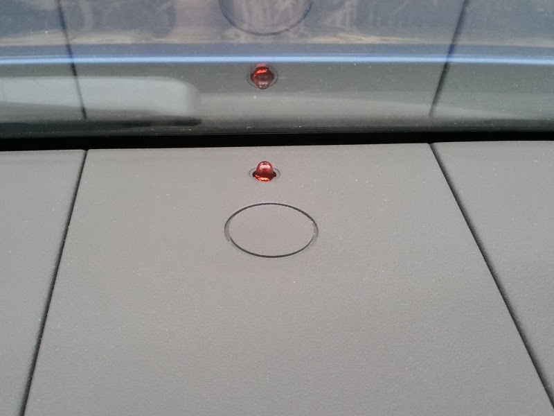
My Saab has one right in the center of the dash, like so:


Sadly, I found the LED to be reaching the end of its useful life. It is still flashing, but the luminosity has dropped to a point where it's only noticeable in very dark setting. For a security feature, this is simply unacceptable to me.

In this post, I will walk through the simple process for a changing that LED.

Saab made this easy, as the LED is mounted on a removable part of the dash.


Be careful when pulling this piece out. Due to years of exposure to the sun and heat, those little plastic tabs are fragile.

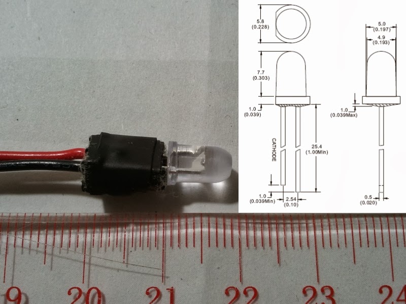
Before going into the actual replacement process, I will talk about the LED itself. The one from the factory is a typical red LED, with an industry-standard size of 5mm diameter. It is possible to change the color, since LEDs come in many other colors. 


The replacement LED I picked is similar, but much much brighter. The lens is clear but the light it emits is still red. Most LEDs have integral optics to produce that focused beam of light. Such effect is not useful in my case, though, as I want a reasonably bright red light emitted in all directions. The trick is to "frost" the lens by rubbing it with fine sandpaper in a circular motion. Also, I "flatten" the top with a file. You will see the difference towards the end of this post.

The LED has two electrical connections, just like the original. One thing to take note is polarity. If the two wires are in the wrong order, the LED will not light up at all.


In my case, I just stripped the wires on both ends and twisted them together. I did this for both wires. Once the twisting is done, I put heat-shrink tubing to protect the bare twisted conductors. I could have used soldering to form a permanent bond, but AC power was not available in the proximity of my vehicle.

The blue plastic thing is an inline splice connector but with its internal cutter removed. The shell clamps down tightly on the wires, and acts as a friction-lock to keep the connections in place. It is optional... but better safe than sorry.


That is all there is to the replacement. There is no fastener to deal with.

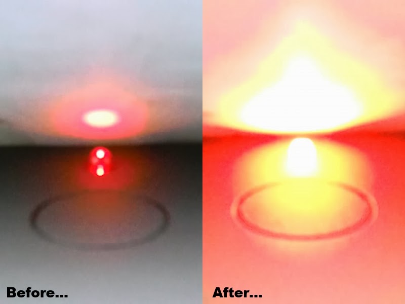
Now the moment of truth:


Please excuse the quality. The camera's auto-focus sensor doesn't like shiny LEDs.
For illustration purposes, a stack of paper has been placed against the windshield.

What a difference!

The brightness is obvious, but notice the effect from "frosting" and "flattening" of the LED.

This is exactly what I am looking for.

2013-09-11

Easy Window Air Conditioner Repair

Recently, a close-relative complained to me about some problems with the air conditioners in his home. The apartment he lives in is a rental property, so replacement is not an option. Since he lacks the necessary repair knowledge, I took a look for him. The repair was surprisingly easy, so I thought it would be a great idea to share.


As illustrated above, his air conditioners are the packaged type that is installed through a wall or window. Such unit is designed to cool a single room.

There were two units with similar problems. The first one I looked at is an old Made-in-China no-name unit, with a cooling capacity of 12000 BTU and uses R-22 refrigerant. The unit runs, but the user complained about compressor shutdown during hot days. On those days, the unit would start up fine and output cool air. Yet, sometime after start, the unit would not cool anymore (but the fan continues to run). If the outside temperature drops, the unit would be back to normal operation on its own.

I was also told that the drain has blocked recently. The user was able to fix that himself. A part of the fix, he rinsed the condenser coils with soap and water. Such testimony led me to believe that airflow restriction due to condenser coil blockage is the cause.

Enough speculating - It's time to take a closer look at the unit. Before I continue, here is a friendly WARNING to viewers who wishes to try repairing their home appliances. Please read the disclaimer on this website. Most home appliances run on line voltage that can serious hurt or kill you. ALWAYS disconnect power before working on the appliance. The unit was unplugged during the whole repair process. If the appliance you need to work on is permanently attached to a connection unit on the wall (e.g. bathroom extractor fan), you have to switch off the power at the circuit breaker first. You should then confirm that the power is indeed off at the connection unit, as it's always possible to switch off the wrong breaker. As always, do NOT attempt the repair unless you absolutely 100% understand what you are doing and what the risks are. 

Obviously, the front cover had to be removed:


Like I mentioned earlier, this is an old unit. The dust and stain shown are typical. The power cable is routed to where the controls are, so there must be something behind the knobs.


There we go. Since the unit utilized non-electronic control, the troubleshooting process was really simple. In fact, the potential culprits are in plain sight - capacitors. The large rusted can (CBB65) is a run capacitor for the compressor, while the black rectangular one (CBB61) is a run capacitor for the fan motor.


CBB65, label = 35 micro-farad ± 5% (33.25 - 36.75)
CBB65, meter = 34.9 micro-farad (0.3% less than labelled value)
CBB61, label = 3 micro-farad ± 5% (2.85 - 3.15)
CBB61, meter = 2.44 micro-farad (19% less than labelled value)

Just as I suspected, the run capacitor for the fan motor is the fault. With a faulty capacitor, the fan runs at reduced speed. This reduced cooling efficiency of the condenser coil to the point that the compressor overheats and triggers the automatic thermal overload shut-off.

Typically, if the meter reading is within 10% then the capacitor is still considered acceptable. The CBB61 here is definitely not. The only method of repair is to replace the faulty capacitor with a new one.

With this unit fixed, it is time to move on to another one with similar but more severe problems. Again, I began by removing the front cover:


This is yet another old Made-in-China no-name unit, with a cooling capacity of 7500 BTU and uses R-22 refrigerant. The unit would hum/buzz when powered on. Since this unit was located in a bedroom, the user rarely uses it due to the noise.

Hum/buzz is a common symptom of a dying capacitor on an electric motor, so I knew this would be another quick one.


The design is common among units with non-electronic control. The large blue can (CBB65) is a run capacitor for the compressor, while the black rectangular one (CBB61) is a run capacitor for the fan motor.


CBB65, label = 17 micro-farad ± 5% (16.15 - 17.85)
CBB65, meter = 16.8 micro-farad (1% less than labelled value)
CBB61, label = 3 micro-farad ± 5% (2.85 - 3.15)
CBB61, meter = 0.737 micro-farad (75% less than labelled value)


Although the multimeter I used was a trustworthy Fluke 87-5, I still couldn't believe the reading at the first test of the CBB61. No wonder the fan motor would hum/buzz like no tomorrow! Just like the previous case, the only method of repair is to replace the faulty capacitor with a new one.

Speaking of the new capacitor:


All the specifications (capacitance, voltage rating, operation temperature rating) of the new one are identical to those on the faulty one. 

It is worth noting that, after the capacitor replacement, both units not only work normally, but also blow much stronger stream of air. 

2013-06-18

My Byte in Raspberry Pi

I can finally get my hands on the infamous Raspberry Pi.


For those who have not heard of this amazing project, the Raspberry Pi is a credit-card-sized single-board computer developed in the UK by the Raspberry Pi Foundation with the intention of promoting the teaching of basic computer science in schools.

The version I got is the Model B, with 512MB memory. While it looks very similar to an Arduino, the Raspberry Pi is not a micro-controller. It is a full computer similar to what you find inside a smartphone or tablet.


Right now, I am not sure what project I will use this on. First attempts at tinkering with it failed, due to power issues. It seems that I need not only a 5V 2A power supply to power the board stably, but also a powered USB hub if I want to use peripherals like USB Bluetooth adapter, USB Wi-Fi adapter, USB to SATA hard drive adapters...

Looks like it's time to get a nice USB hub.

2012-06-03

Easy Fan Repair

A few years ago, my father bought this nice fan.


It's a Sunpentown (Taiwanese home appliance manufacturer) 14" stand fan. It has 3 speeds, infrared remote control, sleep timer, natural rhythmic wind function, etc. Height is adjustable on a telescopic column.

Like many high-end fans on the market today, this fan utilizes an additional small motor, instead of a reduction gear box driven by the fan motor, for the oscillation. In other words, the oscillation is triggered electronically (to power that small motor) instead of mechanically.

The fan worked great until last year, when a strange symptom began to appear. Whenever the fan is running, the fan will abruptly turn itself off if the oscillation is engaged. Selection of the rhythmic wind function will trigger this "instant shut-off" symptom too. Strangely, the fan can start right up again if one presses the on/off button. Other functions like the timer are fine. The on-board 1.5 A fuse has not been blown.

With summer here and fan usage increases, I believe now is a good time to fix this.

Before I continue, here is a friendly WARNING to viewers who wishes to try repairing their home appliances. Please read the disclaimer on this website. Most home appliances run on line voltage that can serious hurt or kill you. ALWAYS disconnect power before working on the appliance. My fan was unplugged during the whole repair process. If the appliance you need to work on is permanently attached to a connection unit on the wall (e.g. bathroom extractor fan), you have to switch off the power at the circuit breaker first. You should then confirm that the power is indeed off at the connection unit, as it's always possible to switch off the wrong breaker. As always, do NOT attempt the repair unless you absolutely 100% understand what you are doing and what the risks are.

Like most repair scenarios, full dis-assembly was the first thing to do. Due to the location, the fan motor housing was the first section I inspected.


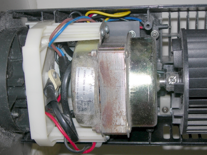
The fan works fine at all 3 speeds, so I believe the fan motor and the starting capacitor are fine. Originally, I thought the small oscillator motor is dead. That assumption is wrong, as a simple hookup to 220 VAC proved that it works. The problem was definitely somewhere else - the base of the fan.

After removing the base (secured with a screw ring) and 6 screws, I found a circuit board that all wires connect to:


On first sight, the fact that the red AC capacitor is connected on the copper side of the circuit board really surprised me. This capacitor is a critical component at the beginning section of the non-isolated capacitive power supply. The power supply is used to generate low voltage for the electronics (LEDs, TRIACs, PIC, etc. - more on these below). It is hard to imagine how this important component was "left out" during circuit board layout (and thus have to be tagged on at the back). Well, enough about that. Let's look at the component side:


First off, a little tour around the circuit board.

The large IC chip is a microcontroller - a PIC16C57C in 28-pin DIP made by Microchip Technology Inc. There are eight LEDs to show fan status like current speed and timer settings. The black component next to the LEDs is an infrared sensor to receive the signals sent by the remote control. Surrounding the 470 uF electrolytic capacitor are five buttons to control the fan. A piezoelectric buzzer (circular black component next to the on/off button) provides audio feedback. On the bottom of the picture, numerous wires connects to the circuit board. From left to right, they are:

Grey - Connects to oscillator motor.
Brown - Connects to fan motor low-speed winding.
Pink - Connects to fan motor medium-speed winding.
Yellow - Connects to fan motor high-speed winding.
Blue - Input from the neutral wire of AC plug.
White - Connects to the motor starting capacitor, then to both motors. Basically a shared live wire after the fuse.
Brown - Input from the live wire of AC plug. Connects to the fuse.

An interesting point I noted was that the first four wires in the list above are all connected similarly. Upstream from each wire is a transistor-looking (TO-92 package) component named "97A8" and a corresponding resistor. A quick search on the Internet showed that it's actually a logic-level TRIAC with a maximum voltage of 600 V. The exact model for this component is MAC97A8. Basically, the TRIAC is like a on/off switch. When one of its legs, named Gate, receives a signal (sent from the microcontroller in this case), AC power is allowed to flow through the two other legs of the TRIAC.

The four TRIACs are in excellent shape so I believe the problem is before the TRIACs. That brings me to the microcontroller. The microcontroller has to be fine. Otherwise, nothing would work. The software (code) is out of consideration because it cannot be modified by this circuit. Looking back at the symptom, and reading this article from Microchip, I believe the malfunction has to do with the microcontroller shutting itself off (reset) due to brown out. It only exists when the rhythmic wind function or oscillation is engaged. I wondered why only these two functions, not other functions like speed change or timer, would cause this. 

By using a flow-chart to analyze how the microcontroller would control the fan if I were to program it from scratch (but with this existing circuit), I discovered an interesting point. When the fan motor is running, only one out of the three TRIACs connected to the fan motor is triggered by the microcontroller at any time. That makes sense because the fan motor cannot be in two different speeds at the same time. Moreover, the oscillator motor can only be turned on when the fan motor is running. To turn on that motor, the microcontroller triggers the corresponding TRIAC. When this happens, the microcontroller is now triggering two TRIACs at the same time. This is also when the "instant shut-off" symptom appears immediately. 

This finding, combines with the fact that the malfunction is likely to be related to age of the fan, turned me to the power supply section of the circuit. It is a non-isolated capacitive power supply with half-wave rectification. Capacitor is almost always the culprit when it comes to unusually-large voltage drop on high load or other weird power issues, and almost always the first type of component to die as time passes, so it's time for a change. 


The capacitors in question were two metalized polyester film (MEF) non-polarized capacitors, both made by UTX and rated for 400 V operation. The large one is "105K" (or 1 uF / 1000 nF) and the small one is "104K" (or 0.1 uF / 100 nF). 

That 470 uF electrolytic capacitor should be replaced as well, but its role isn't as critical as those two, so I didn't touch it.

Replacements are of the same construction (MEF type) and value, but with a higher voltage rating (630 V) and from a different (more reputable, in my opinion) manufacturer - Epcos, which is now TDK-EPC. My point of purchase for the new capacitors was RS Components. After acquiring the components, it's just a simple process of replacement using a soldering iron. 


Since the new capacitors are larger than the old ones due to the increased voltage rating, I had to juggle and be creative with placement. The smaller one fitted in without much difficulty. It's installed at an angle in order to utilize an existing hole on the circuit board.


The big one was not as easy though. Due to the extra-large size, limited board real estate, and re-use of existing holes, I had to use jumper wires. Heat-shrink tubing and electrical tape were added to keep exposed conductors away from the neighbors.


Instead of hanging on the back side of the circuit board, the big capacitor now safely and neatly reside in a space next to the telescopic stand section.

After observing the fan operating for a few days, I am pleased to see that the repair is a success.


2012-05-20

Fix my Saab lights 2

Previously, I shared the discovery, analysis, and resolution of a intermittent problem with headlights. That is not the only commonly-found light-related problem on Saab sedans, however. In this post, I will walk through the same process for a common problem with the glove compartment light.


Just as the image (copyright Saab Automobile AB) above illustrates, the light illuminates the glove compartment. It turns on only when the door to the compartment is open. Well, in theory anyway.

There are two different symptoms to this problem. Either the light remains on even when the door is closed, or the light remains off when the door is open. The latter is an inconvenience, but the former is an inherent danger. If the light is on all the time, it will not only drain the battery (so the car cannot start), but also melt the plastic light fixture. What I have is the later.

At first, I wasn't able to find anything wrong with the fixture. The bulb (10 Watt) is fine. The fixture works fine - light turns off when something is pushing against the plastic actuator; light turns on otherwise. Unfortunately, when I put the fixture back in, the light will sometimes fail to turn on when the door is open.

My gut feeling (and experience) tells me that something weird is happening with the actuator. Originally, I thought the failure had to do with lack of interaction between the actuator on the light and the door mechanism. My observations proved that assumption is incorrect. The door mechanism pushes the actuator only when the door is fully closed; the mechanism moves away as the door opens.

A detailed inspection is needed, so I totally disassembled the whole fixture. After a lengthy test session with a multimeter (I avoid using power because the bulb gets hot quickly), I found the problem:


There is a ridge that prevents the springy metal piece from contacting one terminal of the bulb, if the actuator is being pushed at an angle. It's possible to file down that ridge but the location of the ridge is difficult to get at. A Dremel rotary power tool would be very useful in this situation. Unfortunately, I don't own one.


Time for plan B - Keep the ridge, but elevate the contact surface of the bulb terminal with a BloB of solder. Plan B indeed.


The blob of solder, which is electrically connected to the metal piece, is protruding higher than the plastic ridge. Thus, the springy metal piece makes full electrical contact when the actuator is not being pushed on.

Fix my Saab lights 1

I got to admit, automotive repairs can be as fun/frustrating as IT repairs. If you are like me who enjoy tinkering and troubleshooting, you will know what I mean. Every challenge is a learning experience.

My vehicle is a 2001 Saab 9-3 sedan, with a 2.0 L 4-cyclinder turbo-charged gasoline engine. I'm in Hong Kong, so it's right-hand drive.

The car is now more than ten years old (but only 6x,000 km driven), so minor problems are starting to appear. One problem I am sharing and fixing in this post has to do with the headlights.

The symptom I witnessed is, whenever my car is driven across bumpy road, a headlight failure warning often appears. Interestingly, the headlights (both low and high beams) work fine. Thus, I need to find out where this false-alarm originates from, and create a solution.

According to the many Saab enthusiasts I see on the internet, this is a common problem that has to do with what they called "the orange relay" problem. That alias is not entirely correct, though, as I found out. 

My investigation began with finding the component in question. It is located inside a fuse box in the engine bay (#4; copyright Saab Automobile AB) :


Inside that box, there is indeed a component in vivid orange color, with terminals at the bottom. Saab/GM part number is 4109070. It appeared to be in good shape, so the problem has to be within it. Time to crack it open:


There is a circuit board inside it. On the flip side...


The two ICs on are both Atmel U479B - Automotive Lamp-outage Monitor IC. A datasheet is available in PDF for those who want to understand how it works. Clearly, this is not a relay.

On close inspection, and according to the pointers from various Saab enthusiasts, the problem is related to not the components soldered on the circuit, but the soldering itself. Here is a close-up of the base-end:


You don't need a magnifying glass to see the crack on the right most terminal. If you have one to look very closely, you will find cracks on almost all the terminals. It seems to me that there is too little solder to properly form a solid connection between those pins from the base and the pads on the circuit board. The cracks are in fact vibration fatigue in solder joints. If the vibration is severe enough, the crack enlarges enough to break an electrical connection. The car computer will interpret that as a headlight failure and generate a warning message.

The obvious fix is to strengthen those terminals with a generous amount of fresh solder and flux. 


I am glad to report that I haven't seen the headlight failure warning since the completion of this repair.

2012-03-03

CFL to LED Conversion Experiment

I've always wondered what I could do with those burn-out compact fluorescent light (CFL) bulbs. Driven by interest in solid-state lighting, I performed an experimental project in converting a defective CFL bulb into a functional LED light bulb.

I have done a similar project a few years back, but I didn't save photos to document that. Back then, the goal, which I achieved, was to build an energy-efficient night light.

Enough history... let's get started!

I started with a defective bulb. Remember the saying "a good start is half the success?" It's important to pick the right candidate for the project. Basic requirements are a moderately large base to house the electronics, a standard E27 screw base, and no visible damage.


The two candidates I got were Ikea-brand 7 Watt (Left) and Philips Genie 11 Watt (Right).

I started with the 7 W. Unfortunately, the glass enclosure which protects the fluorescent tubes cracked during the dismantling process. The 11 W opened up fine, thankfully. I used a pair of snip pliers to slowly and carefully cut at the groove that runs around the top end of the plastic body. Due to the hazardous contents inside the fluorescent tube, it is extremely important to cut slowly and carefully in order to avoid breakage of the tube.


The image above shows the empty base without the tubes and the electronic circuit inside it. The green wire is connected to the metal screw casing, while the white wire is connected to the bottom terminal.

On the right side of the image are two more items I used for this project. The black object is a [sanitized] plastic cap from a Listerine mouthwash. The yellow component is a 0.33 uF capacitor. It's X2-type and rated for use on 220V AC line voltage.

Before I continue, here is a friendly WARNING to any viewer who wishes to perform this project. Please read the disclaimer on this website. Do NOT attempt this unless you absolutely 100% understand what you are doing and what the risks are. This project involves line voltage that can serious hurt or kill you.

Speaking of capacitor, this project utilizes non-isolated capacitive power supply to power the LEDs. Such power supply concept is commonly found in places where the power requirement of the device is very low (like a smoke alarm connected to the AC line) and that a transformer or switch-mode power supply is too costly to implement.

The LEDs are from Nichia. Nichia is one of the best LED manufacturers. The four  cool-white LED runs at approximately 10 mA constant-current, and outputs around 25000 mCd.


Because the circuit is non-isolated, the risk of electric shock is apparent. One way to deal with this risk is to eliminate the possibility of user contact to live components. In my case, the circuit is completely sealed inside the plastic casing. Components of the circuit, such as resistors and wires, are all set in place with hot glue. The two halves are permanently sealed together at the end.


The end product is bright, but nowhere as bright as the 11 Watt CFL. Still, it makes a nice night light and a great learning experience.


I will probably make a larger (and brighter) version of this in the future.