2016-01-02

Go with the flow

First of all, happy new year 2016! Yay!

I got the following Kohler hand-shower in Christmas to replace a generic made-in-China cheapo hand-shower.


While this Kohler product is mainly plastic, the whole thing feels reasonably well-made.

One characteristic I really like is that, during the selection of spray pattern settings, there is an audible metallic click from some sort of ball-lock mechanism.

One of the reasons I selected this product is the fact that it is a low-flow water-saving shower. It is advertised as 2.0 G/min., or 7.6 L/min. on average. Upon installation, I am surprised this feature is actually a hindrance. The flow is simply too low for my instantaneous gas water heater to reliably function. 

I did a general search on this issue, and found that the only surefire way to resolve this issue is to remove the flow-limiter built into the hand-shower. 

As always, I tried my best to research on this before actually attempting the removal. Apparently, there are mainly 3 types of flow-limiter:


Time to look at mine. It's easily identifiable at the inlet of the hand-shower.


I used a dental-pick to remove first the retaining ring and then the actual flow-limiter.


It seems this is the turbine design, with reverse-flow prevention. 


This is complete disassembly, FYI. 


Flow-rate is significantly higher now.

2015-11-29

Conquer the Origo Tower

Time for another fan repair post.

Unlike the last episode, this one is a used tower fan - Origo Crudus, also known as FTF36-LED. The fan has 3 speeds, sleep timer, natural rhythmic wind function, etc. One can control it through an infrared remote control, but unfortunately the remote is missing.

The original owner said the fan doesn't work; sometimes the fan will refuse to start. Since the price was real cheap, and, given the symptoms, I'm confident that I can fix it, I bought it for a learning experience.


The first thing I did to it was cleaning. The picture above was taken after hours of vacuuming and sanitizing.

As I powered it on for the first time under my ownership, there was no response except a temperature display:


Perhaps I am optimistic... this is a good sign, as this means the brains (likely a micro-controller) behind everything is working fine.

Before I continue, here is a friendly WARNING to viewers who wishes to try repairing their home appliances. Please read the disclaimer on this website. Most home appliances run on line voltage that can serious hurt or kill you. ALWAYS disconnect power before working on the appliance. My fan was unplugged during the whole repair process. If the appliance you need to work on is permanently attached to a connection unit on the wall (e.g. bathroom extractor fan), you have to switch off the power at the circuit breaker first. You should then confirm that the power is indeed off at the connection unit, as it's always possible to switch off the wrong breaker. As always, do NOT attempt the repair unless you absolutely 100% understand what you are doing and what the risks are.

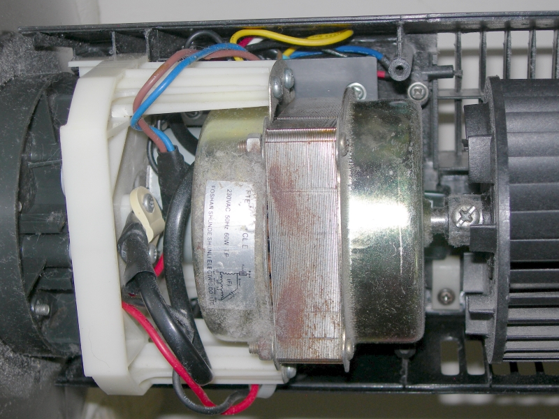
Lets go right in. The following are close-up shots:


This is a 36" tower fan. A LED display and a few push buttons are at the top section, while the fan motor and the oscillation motor are at the base section. A long multi-conductor cable connects these two sections together.

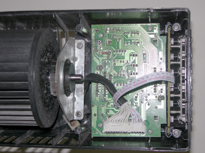
Interestingly, the power supply board, which provides low voltage for the micro-controller, LEDs, TRIACs, and all other electronics, is located at the base section behind the fan motor.

Like the last fan repair scenario, a faulty power supply (due to bad capacitors) was the first thing on my mind. Lets inspect that:


The 1.2 uF CBB61 capacitor on the left is for the fan motor. The large and yellow 2 uF capacitor is a critical component at the beginning section of the non-isolated capacitive power supply. There are five TRIACs to enable the micro-controller to interface with mains voltage control. A very common design.

Learning from experience, I removed the two yellow capacitors for testing:


The ones on the left are bad parts, right are replacements. It is hard to imagine how far off the capacitance values are!

CG-Elec X2 0.1 uF = 0.405 micro-farad (less than 50% of spec.)

CG-Elec X2 2.0 uF = 0.513 micro-farad (roughly 25% of spec.)

Tenta X2 0.1 uF = 0.104 micro-farad (looks good)

Epcos X2 2.2 uF = 1.95 micro-farad (within spec, as B32924 M-class has a tolerance of ± 20%)


Just like my last repair session, I used an Epcos MKP X2 capacitor.


The soldering of the incoming AC wires were a mess, so I fixed those when I put the replacement capacitors in.

This should restore the right amount of power to all electronics, and conclude this exercise. Well, not really.

The fan would turn on (motor spins) when I press the power button. However, if I press the other buttons, like timer or speed, the fan would stop responding. Something tells me there are more problems with this fan. Time to look at the micro-controller circuitry:


The micro-controller is clearly labelled as "MCU1", right next to a buzzer. Noting the temperature display and the fan motor engagement, I know the micro-controller has to be fine. Otherwise, nothing would work.

What's left are the push-buttons:


A quick probing with a multimeter in continuity mode showed that all but two are bad - contact sticking when after being depressed.

This explains the non-responding controls. When buttons are stuck enabled, the micro-controller isn't expecting such situation to happen, thus simply hangs.


The old tactile switches are somehow rusty. This seemed really odd, as the switches are mounted internally, away from the elements like moisture.

I bought a pack of five new switches, so I had to reuse one that is still working.


After replacing the switches, the fan is in full working order.


After observing the fan operating for a few days, I am pleased to see that the repair is a success.

2015-09-15

Ruff Drivers

I recalled that, back in April this year, I read about how a Border Collie took his owner's farm tractor for a ride. The ride was short since the tractor, with the dog as the only occupant inside it, collided (at low speed, thank God) with the barriers in the middle of a highway. Here is a clipping of the traffic report:


Luckily, everyone, including Don the Border Collie, walked out of this accident alive and well. His owner, Tom Hamilton, talked to the media about his dog's unexpected demonstration of driving skills in detail on the Guardian.


Border Collie was specifically bred for intelligence, so I guess it's only natural that some might want to learn how to operate a motor vehicle. Hahaha. Apparently, driving skill/talent in the doggie world is not limited to the Border Collie, as shown by Atom the Pug:


Yes, that is a Pug on the helm of a moving speedboat.

GoPro footage available on YouTube as always.


As if those aren't amazing enough... I saw this next to my house this afternoon:


A mongrel, or mixed-breed dog, expressing interest in a mini excavator.
Tired of digging holes with its own hands, I imagine? ;)


Cute and hilarious.

2015-01-28

Shifter Slider Repair

My Saab 9-3 has a 4-speed automatic transmission. The shifter slider, also known as jalousie or accordion, broke off a few months back. Although this doesn't affect the operation of the shifter, a missing cover will allow small objects to drop into the cavity, and is visually displeasing. It's time to fix this.


Prior to the actual repair, I did a bit of research. The forum at Saab Central is of great help, especially a post written by "win_k" on this subject. Apparently, the whole repair will take less than an hour.

My car is right-hand drive. Saab part number = 4777371

The plastic slider is within the shifter assembly. In order to get to that, the face plate and the shifter stick must be disassembled and removed. The starting point is a Torx 10 screw hidden in the shift lock actuator. 


To fit a screwdriver to the screw, the shifter should be at least pass the third-gear position. It goes without saying that, before proceeding with this repair, the car must be parked on level ground, and turned off with the parking brake fully engaged.

Once the screw is gone, the front half of the shifter stick is free. There is a metal C-clip that holds the shift lock actuator in place. I used a precision screwdriver and a pair of needle-nose pliers to take off the clip. With the clip removed, the shift lock actuator can be removed by pulling it straight up.


 With the help of a butter knife, the face plate is easily pulled off.


The slider has a lump that attaches to the semi-transparent gear indicator strip. These two entities lock together by a 90 degree turn. 


 The slider and gear indicator strip have their own "rails" or "tunnels" to fit into.


At this point, the replacement is complete.

Everything after this is just a reversal of the disassemble process.


The wires for the sport-mode button fit in a special channel inside the stick. 


 Proper routing of the wires is important to prevent pinching and stretching.


 Here are a few important points to note:
A = The T-10 screw goes through this hole on the metal stick.
B = The T-10 screw goes into this hole.
C = The C-clip locks into this groove to secure the shift lock actuator.
D = Terminals for the sport-mode button. Don't forget these connections.
E = Wires should go into the molded trench.


 A close-up of the shift lock actuator. The brass-looking shaft goes through the circular opening. The C-clip is then inserted to lock this whole plastic piece to the shaft.


Mission accomplished.